IRD GLASS
Products / Coatings

Precision Optical Coatings

Anti-reflective, high-reflective, beamsplitter, filter, patterned, conductive, metallic, and high-laser-damage-threshold coatings from UV through infrared.

IRD operates electron-beam and DC magnetron sputtering chambers in-house, which keeps the coating conversation attached to substrate, surface quality, wavelength, angle of incidence, and end-use environment. Send the requirement and the technical team reviews it before quoting — free of charge on a new design.

HLDT capability
>80 J/cm²
At 1064 nm, 1 ms, on IRD's high-damage-threshold mirror stacks. A pulsed fluence figure — not a blanket rating for every coating, and not comparable with a nanosecond or CW number.
Spectral range
UV to IR
IRD designs and applies coatings from ultraviolet through infrared. The achievable stack depends on substrate, angle of incidence, polarization, and operating environment.
Chambers
E-beam + DC sputter
Two electron-beam chambers and one DC magnetron sputtering chamber. IRD offers quick-turn basic coatings in-house; its complete offering runs beyond what those chambers alone cover.

What we manufacture

Coating families

Start with what the optic must transmit, reflect, block, conduct, survive, or reference.

Coating families

The stack follows from what the optic has to do, the substrate under it, and the angle it actually sees — in that order.

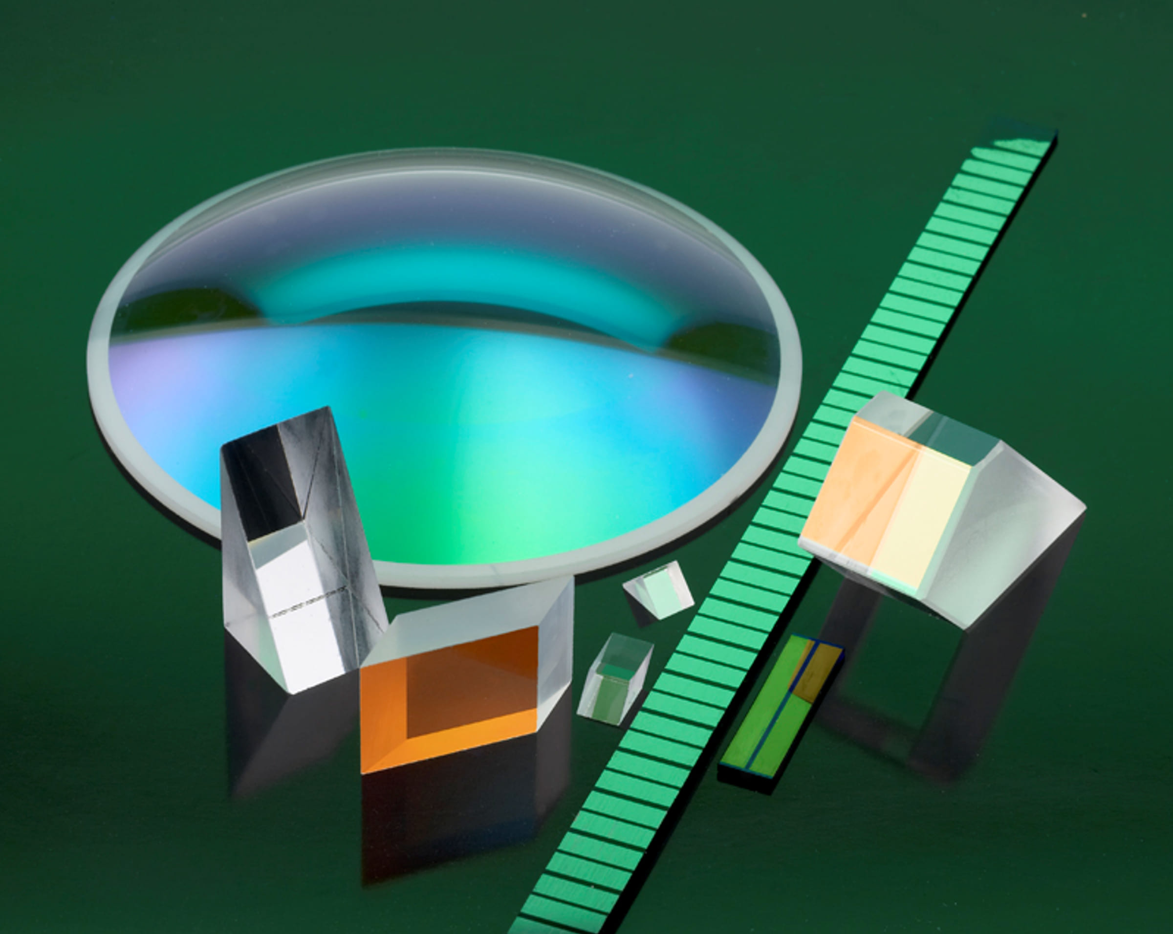
Coated precision optics manufactured by IRD Glass

Anti-reflection

Single-layer MgF2 through high-efficiency multilayer AR, BBAR, and V-coat designs, matched to substrate and wavelength so more of the light reaches the far side of the optic.

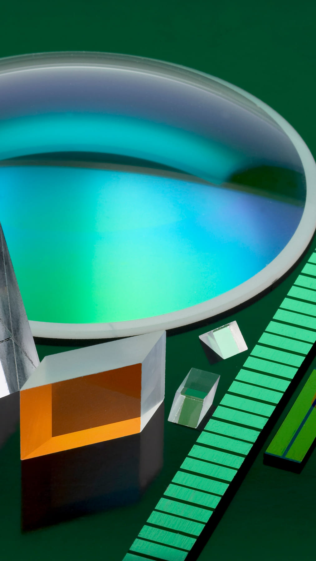
Coated optical components in a range of coating types

Mirrors and HLDT

Protected and enhanced aluminium, silver, gold, and dielectric stacks, ultra-high-reflective mirror coatings, and high-laser-damage-threshold AR and mirror designs.

HLDT capability exceeds 80 J/cm² at 1064 nm, 1 ms
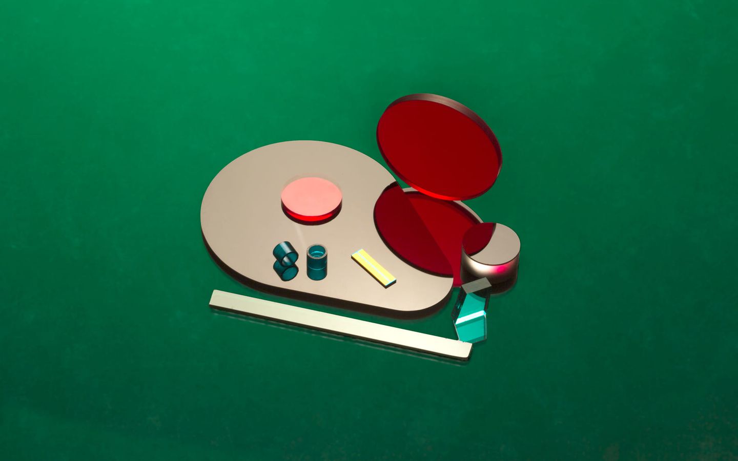
Coated optical filters manufactured by IRD Glass

Filters and beamsplitters

Dichroic, fluorescence, narrow-bandpass, multi-bandpass, edge, and notch filters, with polarizing and non-polarizing beamsplitter stacks developed around wavelength, angle, and system balance.

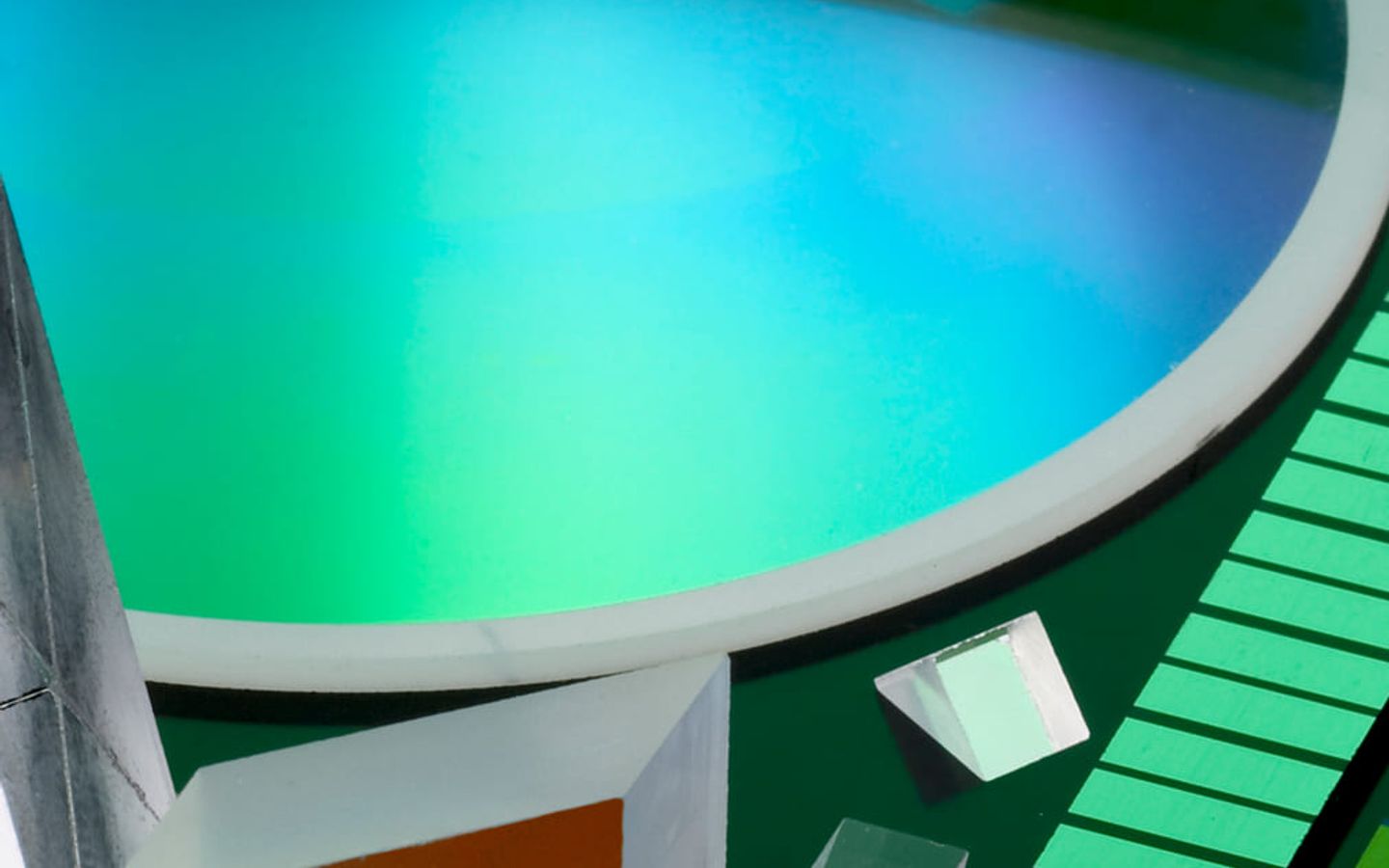
Coated precision optical components

Patterned, metallic, and conductive

Chrome, precious metal, and aluminium patterns for masks, gauges, and datums, plus metallization and ITO conductive layers where the optic is also an electrode or a reference.

Process control

A coating is only as good as the surface under it

IRD's own high-damage-threshold research is explicit that damage threshold is largely determined before any layer is deposited. These are the controls that decide whether a coating run succeeds.

The substrate is decided before the stack is

Substrate composition and homogeneity, surface finish, subsurface damage, residual stress, polishing and cleaning residue, dust and other contamination, and the coating-substrate pair all contribute to damage threshold. Fabrication runs staged fixed-abrasive grinding and loose-abrasive lapping so each step removes the micro-cracks left by the one before it.

Polishing target for high-damage-threshold optics: better than 10 Å rms

Cleaning is specified per component, not per shop

Hand cleaning with isopropyl alcohol, cascaded detergent baths, deionised-water rinsing, oven baking, spin drying, proprietary solvent washing, and hydrofluoric acid etching for stress relief. Most high-damage-threshold optics get a cleaning process built for the part rather than a general optics clean.

Edge geometry and masking are designed in, not fixed later

On one high-power mirror program, sharp slot edges shed fibres during cleaning and those fibres became coating defects that pulled the damage threshold down. A 50 µm bevel — the maximum the clear aperture allowed — plus a cleaning process built around it solved it. That decision belongs at design review, not after polishing.

Deposition method follows the design

Electron-beam evaporation and DC magnetron sputtering are different tools with different strengths. IRD's coating engineers select the method against the design and substrate, and run single- and multi-layer metallic, broadband, V-coat, polarizing, and HLDT stacks across both.

Capability ranges.Specify what the system needs.

Coating feasibility is defined by the complete optical requirement. Provide substrate, clear aperture, spectral target, angle, polarization, environment, and inspection method.

AttributeTypicalBest caseApplication note
DepositionElectron beamDC sputtering availableMethod selected by design and substrate
Laser damage thresholdApplication-defined>80 J/cm² at 1064 nm, 1 msHLDT stacks on laser-quality substrates
Spectral coverageVisibleUV through IRApplication-specific stack design
Layer structureSingle layerComplex multilayerAR, HR, beamsplitter, and filter stacks
PatterningFull apertureCustom patternChrome, metals, masks, and datums

These are IRD's published capability figures, not a guarantee for a given stack. Reflectivity, transmission, and damage threshold all depend on wavelength, polarization, angle of incidence, and the substrate beneath the coating, and IRD's published values do not state those conditions — send your operating conditions and the team will confirm against them. IRD does not publish in-house laser-induced damage testing, so treat the 80 J/cm² figure as a reported process capability rather than a certified per-lot result.

Coated optical filters manufactured by IRD Glass
Cell-based production

The coating is part of the component, not a final decoration.

When fabrication and coating are reviewed together, edge handling, masking, cleaning, fixture contact, witness samples, and inspection can be designed into the process instead of resolved after polishing. That is the practical argument for coating at the same supplier that made the substrate.

The IRD Advantage
3
Coating chambers in-house — two e-beam and one DC magnetron sputtering
>80 J/cm²
Reported HLDT capability at 1064 nm, 1 ms
98%+
On-time delivery, past decade
Application fit

Materials, forms, and uses

Use these lists to frame the first review. The drawing, environment, performance requirement, inspection method, and volume determine the final route.

Performance

  • AR / BBAR
  • High reflection
  • HLDT
  • Bandpass
  • Notch and edge
  • Polarization

Materials

  • Dielectric stacks
  • Aluminum
  • Silver
  • Gold
  • Chrome
  • ITO

Inputs to quote

  • Substrate
  • Wavelength range
  • Angle of incidence
  • Polarization
  • Damage threshold and environment
  • Acceptance data and test method

Production assurance

ISO 9001:2015Certified quality management system covering both Minnesota facilities. The system is certified — an individual part is not.
ITAR registeredRegistered with the DDTC. Controlled programs are manufactured and stored domestically in Minnesota.
98%+ on-timeIRD-reported delivery performance, sustained across the past decade.
Review quality & certifications
Keep researching

Related products and industries

The finished component often crosses product categories. These pages cover the nearest materials, processes, and program contexts.

Coated precision optical components
Start with the print

Send us your precision optical coatings requirement.

Send the substrate and its surface specification, the clear aperture, the spectral target with tolerances, angle of incidence, polarization, damage-threshold requirement with its wavelength and pulse conditions, operating environment, annual volume, and the acceptance data and test method you need with the parts. For a new design, the technical team runs a no-cost Design for Manufacturability review before quoting.

Or call 320.693.7217. If IRD is coating your substrates rather than its own, send the incoming surface specification too — it usually sets the ceiling on what the stack can do.