
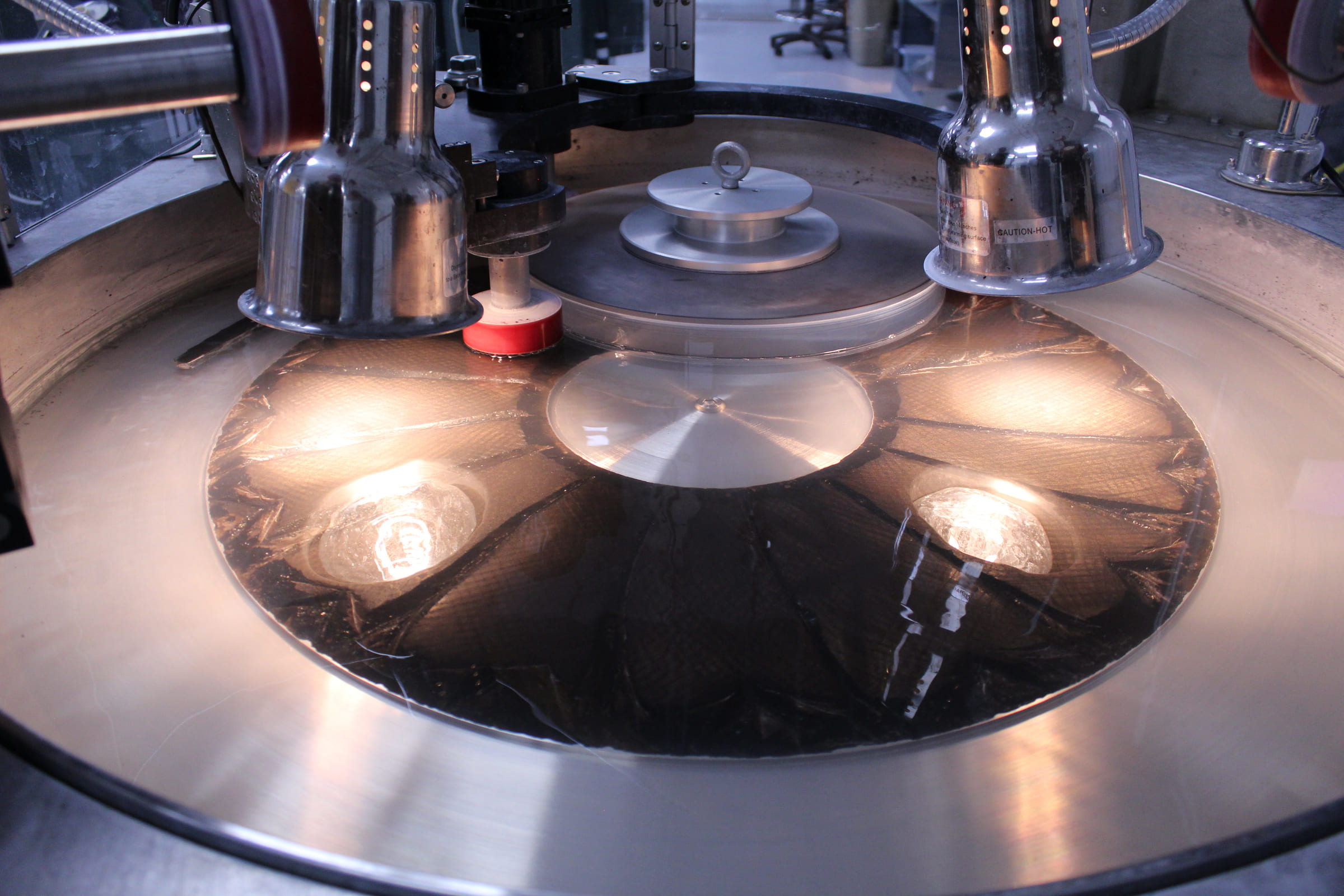
Equipment is only useful when the process is controlled.
IRD combines CNC machining, precision grinding, lapping, polishing, sawing, dicing, waterjet cutting, cleaning, coating partners, and metrology inside dedicated manufacturing cells.
The machine list helps engineering teams self-qualify a supplier. The more important question is how the equipment, operators, fixtures, inspection plan, and documented work instructions stay aligned from first article through repeat production.
- 30 × 16 × 16
- Max machined part, inches
- 16″ dia
- Max polished optic
- 40 × 24 × 2
- Waterjet envelope, inches
Process equipment by job to be done
Grouped by the job each machine does, so you can connect a feature on your drawing to a practical manufacturing route. The specific machine and cell assigned to your part are confirmed during review.
CNC machining and turning
Create complex geometry, holes, slots, profiles, and precision mechanical features in brittle materials.
- Multi-axis CNC machining centers
- Swiss-style turning for small precision parts
- Diamond tooling and application-specific workholding
- Custom fixtures developed for repeat production
Grinding
Control size, form, concentricity, and surface condition before lapping or polishing.
- Surface grinding
- ID and OD grinding
- Centerless and cylindrical grinding
- Profile and form grinding
Lapping and polishing
Develop flatness, parallelism, surface roughness, and optical finish.
- Single- and double-sided lapping
- Precision optical polishing
- Pitch and engineered polishing processes
- Dedicated tooling for repeat programs
Cutting and blank preparation
Convert sheet, plate, rod, and boule stock into controlled blanks before finish operations.
- Precision sawing up to 14 × 8 × 1 in
- Dicing up to 8 in diameter × .300 in thick
- Waterjet cutting up to a 40 × 24 × 2 in envelope
- Edge preparation and controlled cleaning
Inspection and metrology
Verify dimensional, surface, angular, and optical requirements against the drawing.
- OGP non-contact vision measurement
- Zygo NewView white-light interferometry
- Laser interferometers
- Nikon autocollimators
- Contact dimensional measurement and calibrated hand tools
Finishing and supply-chain support
Complete the component around the core fabrication process and keep responsibility in one program path.
- Cleaning and packaging for application needs
- Coating coordination and inspection
- Outside-process control where required
- Traceability and documentation through final inspection
Capability inmeasured terms.
Every tolerance IRD holds, with the maximum part envelope for each process. These are manufacturing capabilities, not automatic specifications for every geometry and material — final feasibility depends on the complete drawing, material condition, feature relationships, inspection method, quantity, and schedule. Materials run across all of these processes include glass, ceramic, sapphire, spinel, quartz, and ZERODUR®.
| Process & attribute | Typical | Best case | Context and max envelope |
|---|---|---|---|
| Machining — dimension | ±.005 in | ±.0001 in | CNC milling, Swiss turning, drilling; max part 30 × 16 × 16 in |
| Machining — flatness / parallelism | ±.005 in | ±.002 in | Machined faces before grinding or lapping |
| Machining — radius | ±.005 in | ±.002 in | Profiles, corners, and formed features |
| Machining — roughness | Ra 30 µin | Ra 10 µin | As-machined surfaces |
| Grinding — dimension | ±.002 in | ±.002 in | ID, OD, surface, and profile grinding; max 24 in dia × 6 in ht |
| Grinding — flatness / parallelism | ±.001 in | ±.0002 in | Hard materials and structural geometry |
| Grinding — radius | ±.005 in | ±.001 in | Formed and profile-ground features |
| Grinding — roughness | Ra 40 µin | Ra 10 µin | Ground surfaces before lapping or polishing |
| Lapping — flatness / parallelism | ±.000050 in | ±.000010 in | Seals, spacers, tooling, references; max 13.3 in dia |
| Lapping — roughness | Ra < 10 µin | Ra < 5 µin | Single- and double-sided lapping |
| Polishing — roughness | Ra < 1 µin | Ra < 5 Å | Optical faces, windows, mirrors; max 16 in dia |
| Polishing — flatness | 1 wave | < 1/20 wave | Wavefront-critical surfaces |
| Polishing — parallelism | 30 arc sec | < 5 arc sec | Windows, filters, and plane-parallel optics |
| Polishing — angle | 5 arc min | 3 arc sec | Prisms, wedges, and alignment geometry |
| Sawing — dimension | ±.005 in | ±.001 in | Blanking and sizing; max 14 × 8 × 1 in |
| Waterjet — dimension | ±.010 in | ±.005 in | Profiles; work envelope up to 40 × 24 × 2 in |
| Dicing — dimension | ±.005 in | ±.0005 in | Small-format parts and arrays; max 8 in dia × .300 in thick |
A machine does not make the process transferable.
Difficult glass, ceramic, sapphire, and infrared components depend on workholding, tool condition, process sequence, cleaning, inspection correlation, and the judgment of the people running the cell. IRD's cell-based model keeps those variables with the program instead of rebuilding the process around whichever machine happens to be open.
For qualification, ask about the assigned route, measurement method, lot controls, change management, and what documentation will ship with the part.
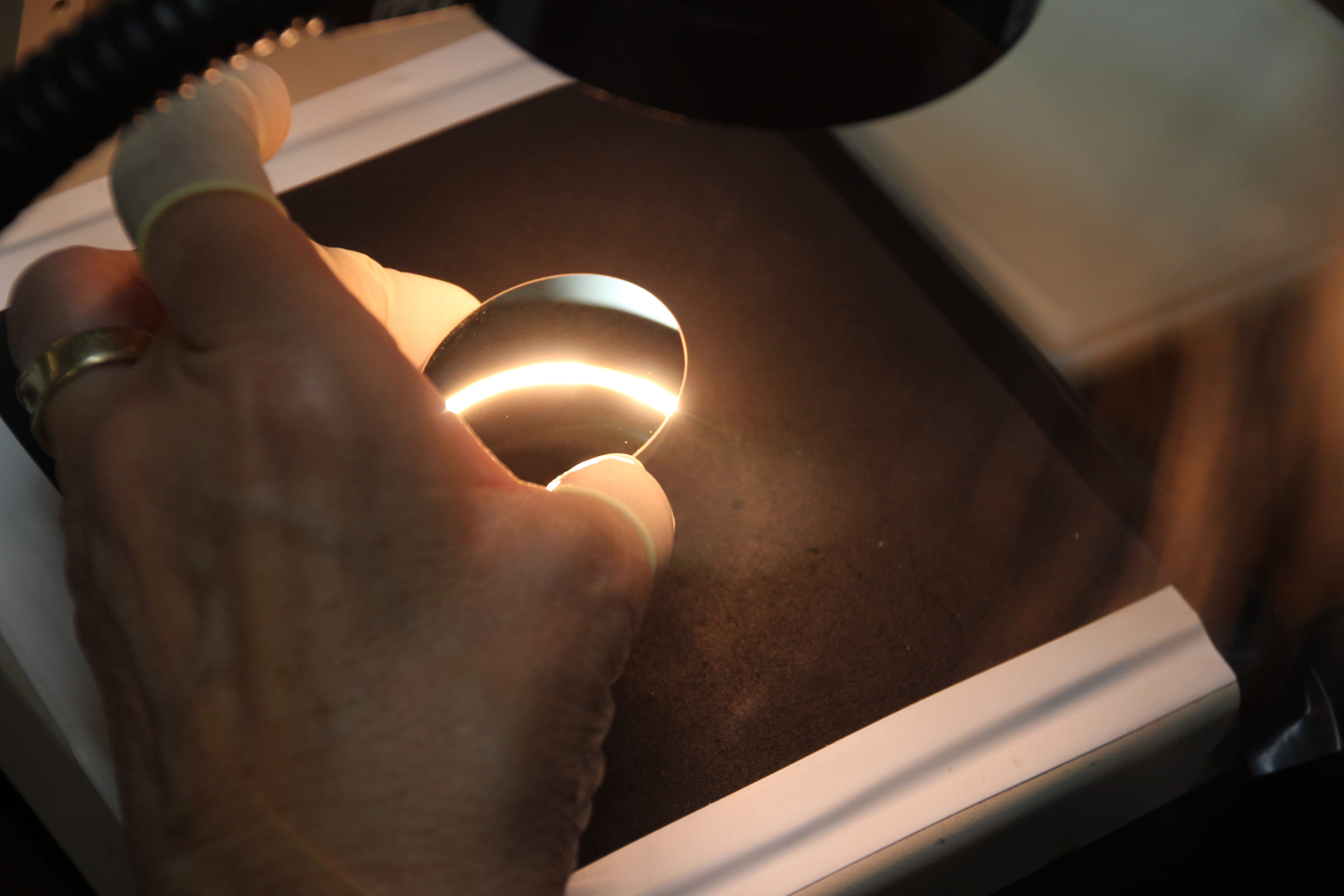
Put the equipment list against your print.
Send the drawing, material, quantity, critical features, inspection requirements, and target schedule. The applications team will identify the likely process route and any questions that affect manufacturability.